Cnc Limit Switch Wiring Diagram the wiring never sleeps
Limit switch test: Test if PlanetCNC TNG software recognizes limit switch activation. On main screen click "IO" tab and observe controllers Limit behavior: Invert option: If you use normally closed type of limit switches then you can invert controller limit input in settings: File/Settings/Motors -> Limit Switches
Limit Switches a better way Spark Concepts
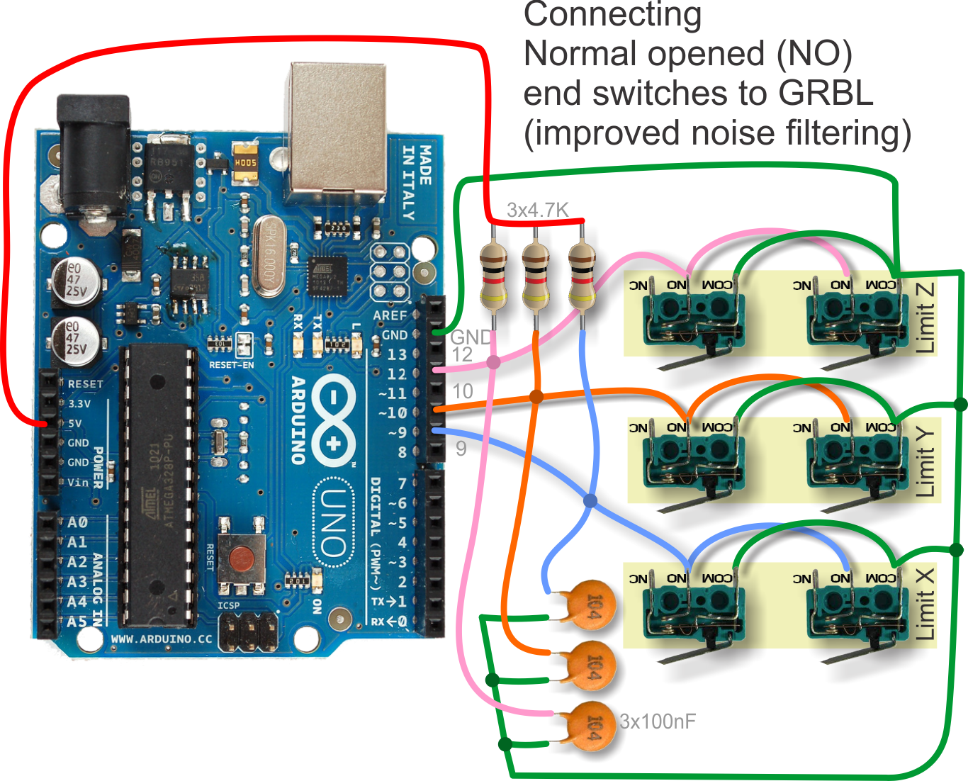
This video is about Grbl 1.1 Limit & home switch Guidehttps://github.com/gnea/grbl/wiki/Wiring-Limit-SwitchesGrbl Arduino CNC Wiring Limit Switcheshe limit s.
Cnc Limit Switch Wiring Diagram Arduino diagram definition
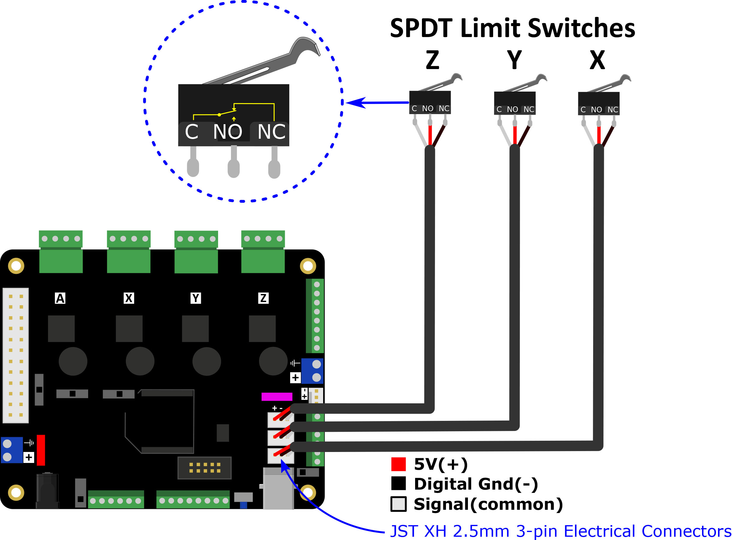
In the Endstops row, connect pin 3 (White) to the Sig pin for each respective axis. Connect the Black and Green wires to the "-" negative on the Separate Power IN in the upper left hand side of the board. Up to 2 endstops can be wired into this terminal. Connect pin 2 (Red with resistor) to the V+ on the Endstops row.
Cnc Endstop Wiring Diagram Wiring Diagram Pictures
Setting up Home and Limit switch hardware on a CNC machine can offer many great benefits when operating an automated tool. This video will focus on the physical switches themselves, such as.

Cnc Limit Switch Wiring Diagram Arduino diagram definition
WorkBee CNC Limit Switches & Wire Routing 6 A. Carefully attach the Limit-Switch that was inserted in Section 2.1.5 to a Limit-Switch- Plate using 2 x Plastite-Screw-M3-8mms. The Plastite-Screw-M3-8mms self thread, the best technique is to screw in a couple of turns, then back out, and then back in a
3 Wire Limit Switch Wiring
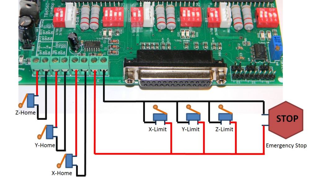
Typical Limit Switch Configuring LinuxCNC for limit, home and probe inputs I have wired 5 lines: Z Home, X Home, Y Home, Limit and Probe. Here is how I configured the LinuxCNC system using the StepConfig wizard.

CNC Grbl breakout shield CNC Design Limited
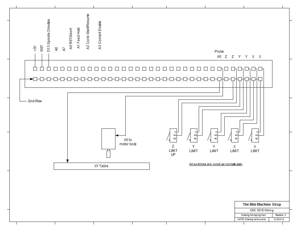
How to Install Limit Switches in your Genmitsu 3018 Pro with Only Your CNC. Updated 2 years ago by George Based off of the works of Corey V. This project file and tutorial are designed for the SainSmart 3018 Pro.. After the milling operations are run, measure the lengths of wire you will need for each limit switch. Cut wire to length and.
21 Images Cnc Limit Switch Wiring Diagram
How to connect and set limit switches Limit switches are used for reference (homing procedure) and as a safety feature. In order that software recognizes limit switch activation and makes appropriate action, we need to configure limit switch inputs in settings: File/Settings/Motors/Limit Switches.
Cnc Limit Switch Wiring Diagram Wiring Diagram
Limit switches (also referred to as end stops or homing switches) are sensors that sit at one or both ends of each movement axis of a CNC to provide a few different functions. There are many different limit switch designs which broadly fall under being either mechanical or non-mechanical (ex. inductive).
Cnc 3018 Limit Switch Wiring Diagram Wiring Diagram and Schematic Role
When you have home switches, you simple press the "Ref" button to reference an axis, or "Ref All" to reference all axes. When you do this, Mach knows to move the mill axis in the positive direction until exact instant the home switch closes and then back off slightly until it opens again.
Introduction to CNC for a Total Novice Setting up a Laser SainSmart Resource Center
Each axis can have two limit switches: one for the ++ (positive) end and one for the -- (negative) end. The positive end would be the limit switch at the end of the machine that, say the machine has a 4'x8' area, reaches a bit after the 8 foot mark. The negative end would be the limit switch behind the 0 foot location behind the origin.

Wiring The Cable Arduino Cnc Limit Switch Wiring
A limit switch is a way of physically detecting when an axis reaches the limit of its travel and automatically stop the machine. This has a few uses: Prevent skipped steps or even damage to the frame, motors, or other parts of the machine. To enable homing on each axis. What is homing?
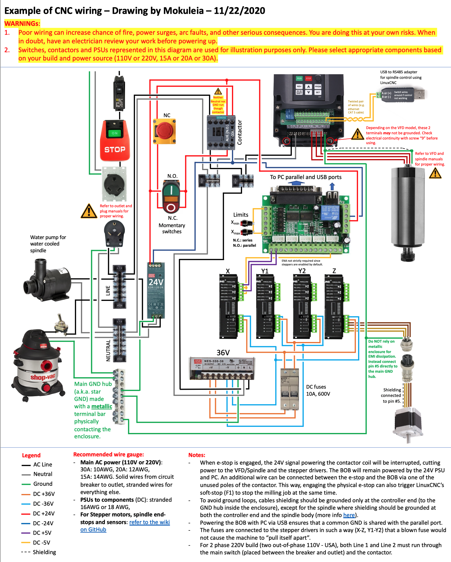
PrintNC Wiring Diagram Peter Verdone Designs
What are CNC Limit Switch Wiring Diagrams? At its most basic level, a CNC limit switch wiring diagram is simply a visual representation of the electrical connection within a given device.
Cnc 3018 Limit Switch Wiring Diagram Wiring Diagram and Schematic Role
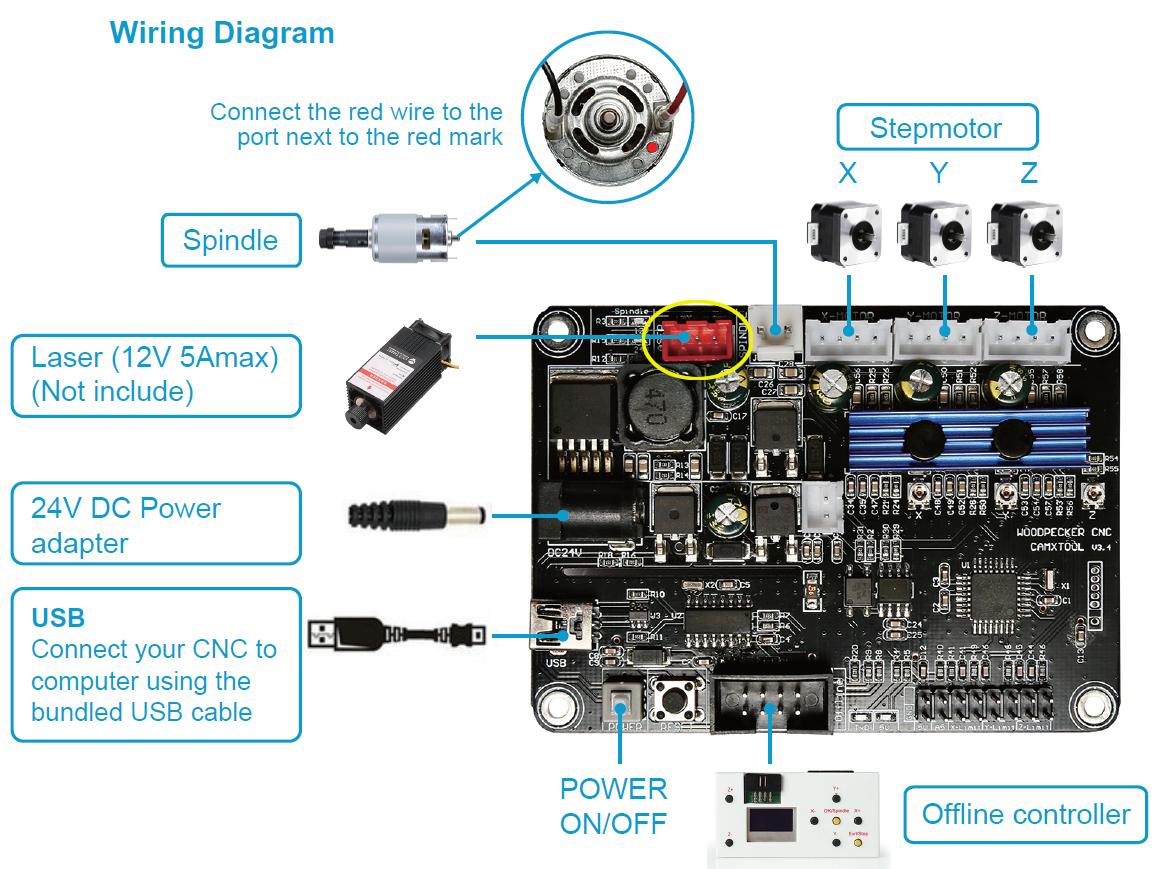
This is a continuation of my prior blog on limit switch mounting hardware design for the CNC3018. There are plenty of resources on various limit switch wiring. As with most information on the internet: some is good, some not so good. One place to start for the desktop CNC is the gnea/grbl wiki: Wiring Limit Switches. One of the first things to note is the Woodpecker board is designed such the.

Tech Crew Cnc 3018 Limit Switch Wiring Diagram
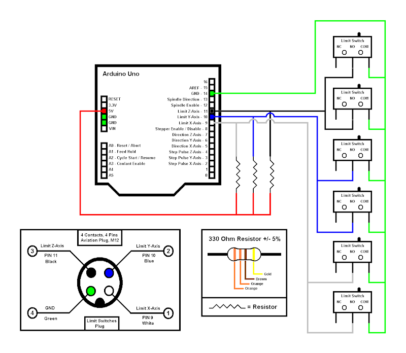
Typically, there are two limit switches per axis, and all are wired in series - such that if any one switch is 'tripped' (e.g. "opened"), it will break the circuit and shut down the motors. All limit switches can be wired to use just one input pin on the HobbyCNC board. You CAN use pin 11, 12, or 13.
limit switch cnc wiring diagram Wiring Diagram
Originally Posted by john-100. the diagram on page 8 of the G540 manual just shows home switches for 4 axis. G540 REV8 Manual.pdf. assuming your using mechanical micro switches not electronic proximity switches. you can add another normally closed switch to the switches shown in the G540 manual.